
How most carburettors work...
Variable Venturi
Kawasaki Z1’s are fitted with Mikuni slide carburettors. Another name for them is variable venturi. The carb has a hole roughly 28mm diameter passing from front to back. In the middle is a venturi or slide which is a restriction within the carburettor designed to speed up the air flowing through the carb. We call the venturi a throttle slide. Remove all four slides and the engine will run at one speed only, flat out. Because we want our engine to operate at various speeds we introduce the venturi {slide} which changes the cross sectional area of the 28mm hole enabling us to drive at the desired speed.
If a descending piston creates a vacuum (depression) of -15psi and atmospheric pressure is +15psi then usual carburettors can be said to have a working range of 30psi. Increasing their ability to fill the combustion chamber is decided by the limitations of physics.
There are three holes in the rear of a carb. One of them allows air to pass along the hole, past the air mixture screw, over the slow running jet where it draws fuel and into the combustion chamber. The same amount of air always passes down the hole. Air mixture screws change the cross sectional area of the hole by restriction. The same amount of air will pass but at a different rate.
Common faults
Hesitation or flat spot:
Kawasaki specify that the c clip of the slide needle be positioned on notch three for A models and notch two for B models. If you are using replacement carb kits with slightly different needle and main jet set them all on notch three.
Won’t shut down 1:
Slide height of 0.70mm is critical, to high and the engine is slow to shut down. Prove by removing the tick over screw. Should rev and shut down in the desired manner.
Won’t shut down 2:
Caused by a long spark particularly when using new spark plugs. The plug insulation has broken down and the spark plug voltage is jumping a greater distance to earth. Weak spark changes ignition and combustion characteristics.
Fuel overflow 1:
Assuming the height of the fuel is correct. The fuel tap causes the sporadic spurt out of the tube. Changing the fuel height will not cure the problem because the fuel seat needle within the carburettor regulates flow in use and is not an effective shut off valve.
Fuel overflow 2:
Assuming the height of the fuel is correct and the fuel tap is working effectively then the floats are sticking. Change the float pins and insert pipe smoker cleaners along the bore of the float.
Excessive gap between tickover screw and lifter lever:
One or more of the slides has bottomed out on the slide floor. Further adjustment turns the common rail lifter bar clockwise.Start again and reset.
Carburettors
Kawasaki Z1 owners are blessed with a good workshop manual with the exception of the chapter dealing with carburation.
Information about adjustment is misleading and out of date. The notion that the average owner can turn the pilot air screw and observe a difference or set slide height using vacuum make matters worse. Ignore the information, the description is correct when applied to a single cylinder, single carb circumstances.
Mikuni describe carburettor adjustment as a necessary process to keep four cylinders running at exactly the same speed, where each cylinder on the motorcycle is a separate engine. In order to match the speed of each cylinder to one another, the slide position must be exactly the same on each carburettor on the basis that each cylinder has the same compression ratio, perfect ignition timing and mixture quality.
In these circumstances all cylinders will run at the same speed. Further on they recommend getting rid of vacuum or stick gauges for set up purposes and confirm that their use be limited to final adjustment once things are 95% correct when set mechanically. They are correct. They can’t do it and neither can you because the vacuum shown on the gauges is a result of cylinder compression, spark quality, ignition timing, length of spark, mixture quality, valve lift and so on. If one of these parameters differs from those of another cylinder it will become increasingly difficult to set the slide heights using vacuum.
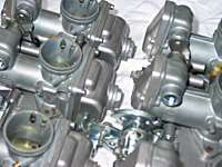
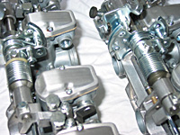
Carburettor Variation
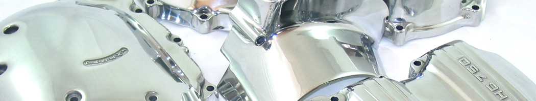
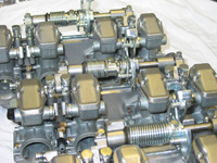
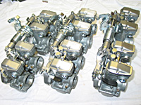
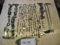
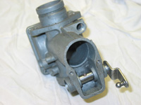
There are six types of Z carburettor. Obvious differences are float bowls and carburettor body. Both Z1 and Z1A have three differing push pull arrangements. Z1B carburettors also have three variants. The images show some differences.
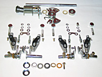
Restoration
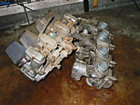

A typical set of early carburettors.
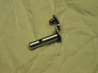
1. Place a straight edge along the flat part of the three bolts that secure each lifter mechanism and push pull butterfly. If necessary undo the bolts about one quarter of a turn to ensure the flats of the three bolts are parallel. If the straight edge rocks the common push pull shaft is twisted and a substitute is required. I make new ones from time to time out of 10mm diameter silver steel. Should you make your own do not assume that stainless bar is a better alternative, you will find it difficult to drill also it is not as bright as silver steel
2. View the control cable guide, it should not be bent but may be twisted. Both U shaped cable holders should align with the push pull butterfly below. Twist is easily sorted out with an adjustable spanner
3. Damage to the push pull butterfly is best resolved by substitution although the minor problem of a bent nipple holder can be resolved with a screwdriver.
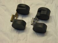
4. Remove all tin parts including the blanking discs located at the top of each carburettor. Blanking discs can be tapped out when a minor amount of heat is applied. Great care must be taken because carburettor aluminium will melt at low temperature. Do not send parts with corrosion sore witness marks for zinc coating. Linish and dress the damaged parts.5. About lifter levers…they can be straightened but not zinc or chrome plated. They are hard chromed and attempts to brighten the visible part will result in disaster to the shaft.
6. Early Z’s have a grub screw and half nut fixing the choke lifter to the choke lever. Turn out the nut to the top of the grub screw, heat with MAP gas blowlamp until red. The screws should come out without breaking using this method.
7. Strip each carburettor ensuring each slide is numbered one to four. No need to number the carburettors.
8. The brass/stainless part of each float should be flat and level, not bent up or down, the fuel shut off tang should also be flat.
9. Mask and plug all openings.
10. Pre clean outside of each carburettor with vapour blaster.
11. Carburettors are not pure aluminium. The manufacturers introduce additives for numerous reasons. Vapour cleaning alone will not clean them adequately. The surface has to be smutted by immersion in mild acid and the surface smut removed by a further blast. They appear white clean however, this finish is superficial and the white glass precipitate appearance will soon disappear in bad weather.
12. Ball burnish the parts
13. Carburettor tops can be lacquered electronically. Pre cleaning in this process delays the onset of corrosion and subsequent lifting of lacquer. Lacquer films refract light and effect the colour of aluminium so tops should be as white as possible. I use scouring wheels.

14. New carburettor kits are adequate. The emulsion tube is re-used after cleaning in solvents and nitric acid. Obtain a set of wire gauges and rod all airways. The cast lug part of the carburettor into which the emulsion tube is screwed may contain petrol jelly deposits. Look down the snout and clean.
15. Blow compressed air through seven openings two of which are critical. If air cannot be felt coming out of the small pilot airway within the carburettor bore just in front of the slide then, the carb is scrap. Air should also come out of the bottom of the cold start tube. If it is blocked rod clean with wire gauge or replace…comes out easily with judicious heat and pliers.
16. Assembly descriptions within CLYMER manuals are adequate. The photograph shows location of each part, however the 4 lifter arms shall be checked… Lever lift arms shall not move up or down when inserted into the carburettor body. If the bush is worn or the slippy insert missing a repair is required. The bushes can be pressed out and a steel bush inserted. Alternatively a couple of brass bushes can be turned on a lathe and inserted.
Set-up
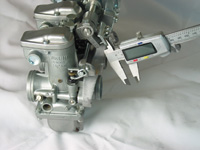

1. Unscrew each slide height adjuster so that bottom of each slide is away from the bottom of the carburettor bore.
2. Turn throttle stop screw inwards. Manual specifies a distance of 10mm between lever B and throttle stop plate.
3. Set the distance between the throttle butterfly and throttle stopper at 1.5mm by repositioning the throttle stopper.
4. Technical writers understand that the average owner does not have access to precise measuring equipment so they recommend the next best thing which requires you to turn down the slide height adjusters almost to the bottom of the carburettor floor ensuring that a 0.7mm thick piece of wire can be inserted between the bottom of the throttle slide and carburettor floor. I would use a piece of wire 0.5mm diameter because this will increase depression and encourage easy bouncy starting without choke. Warning turning one of the adjusters to far will cause the slide to bottom out. It is possible to carry on turning it further because the common steel lifter rod turns about its axis, lifting the other three slides. You will notice a gap between the throttle stop screw and lever B. Should this occur, start again.
5. Nipping up the adjuster screw locknuts will change the clearance between slide and carburettor. I would make final adjustments with the locknut almost tight to minimalise this effect.
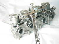
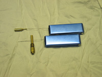
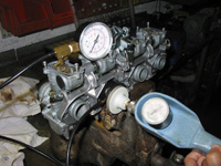
I have a valve seat testing tool, compressor and spare vacuum gauge. The photograph shows the simplicity of this technique. Each slide height is positioned so that the correct amount of air passes through each carburettor. It has the added advantage of taking into account the wear between slide and carburettor body.
Slide height is the most important aspect of synchronisation. Get it wrong and the engine will tick over at the wrong rate. Adjustment of the tick over screw may cause slow shut down when the throttle is snap shut.
6. Air mixture screw settings are limited; there is little the average owner can do. The best method requires vacuum in order that each airway is obstructed the same amount. Stay with manual settings.